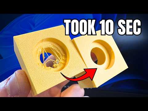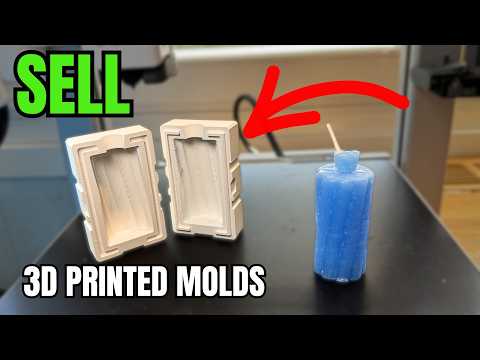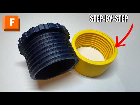
About this video
Video by Vitek Innovation: Instagram Profile
What Is a Snap Fit and Why Model It in Fusion 360?
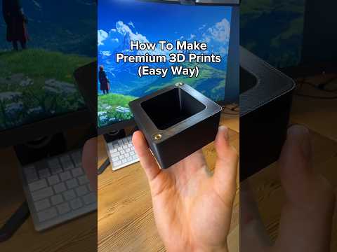
A snap fit is a mechanical joint that holds two 3D printed parts together using a flexible cantilever or tab that deflects during insertion and then locks into a matching undercut. It's one of the most useful joints in 3D printing because it requires no screws, glue, or hardware — just clever geometry.
This Fusion 360 snap fit tutorial walks through the entire workflow using a simple slot-style design. It's a great project for anyone learning Fusion 360 for 3D printing, especially beginners building enclosures, cases, or modular prints.
Step 1: Modeling the Base Body
Start on the Top Plane and sketch a square (20 mm × 20 mm) centered on the origin using the midpoint constraint. Inside that square, sketch a slot profile made from three connected arcs/centers:
- Center-to-center distance: 8 mm
- Slot radius: 3 mm
- Insertion gap width: 2 mm
Use a construction line from the origin to the slot's midpoint to keep the geometry symmetrical along the red axis. Convert the helper line to construction (press X or right-click → Construction) so it doesn't interfere with the extrude.
Step 2: Extruding the Slot and Insert Hole
Extrude the base square symmetrically 10 mm each side (20 mm total). Then re-show the sketch and extrude the slot cutout 5.5 mm deep — that extra 0.5 mm gives the male insert clearance to enter cleanly. The deeper receiving pocket should match the snap tab's height (5 mm) so the two halves align flush.
Step 3: Building the Male Snap Insert
Create a second body by extruding the same slot profile 5 mm downward. This becomes the cantilever tab that will flex and click into the base.
Step 4: Sketching and Sweeping the Snap Profile
On the middle plane of the male insert, project the side wall (shortcut: P) and sketch the classic snap-fit profile:
- Two equal circles (1.1 mm diameter) made tangent to each other
- A tangent line connecting them
- Position the profile 2 mm above the bottom of the wall
Finish the sketch and use the Sweep tool to cut the profile along the top edge of the wall. Fusion 360 will hollow out the full length of the tab in one operation.
Step 5: Adding Offsets and Tolerances (Critical for 3D Printing)
Tolerance is everything in a printed snap fit. The video uses:
- -0.3 mm offset on all swept faces (general clearance for the male part to slide in)
- -0.15 mm additional offset on the bottom locking faces only (so the snap can actually release)
Without that second offset, the joint would be too tight to open after printing.
Step 6: The Flex Hole and Second Sweep
Sketch a small arc on top of the male insert — a flex window roughly 3 mm wide — to give the cantilever room to bend. Cut it through the body and extrude it 10 mm down to match the base body depth.
Finally, reveal the second sketch and sweep it along the bottom edge of the same body to create the matching insertion tongue.
Pro Tips for Fusion 360 Snap Fits
- Always keep sketches clean and use construction lines for symmetry
- Use the
Pshortcut to project edges — much faster than the menu - Hold the left mouse button to cycle-select hidden geometry
- For FDM prints, leave 0.2–0.4 mm clearance; for SLA/resin, 0.1 mm is usually enough
- Print snap fits vertically along the bending axis for maximum strength
FAQ
What tolerance should I use for a 3D printed snap fit?
Around 0.3 mm total clearance works for most FDM printers. Resin prints can use 0.1–0.2 mm.
Can I scale this design larger?
Yes, but scale the slot radius, insert gap, and offset values proportionally. Thin tabs break easily on large parts.
Do snap fits work without a flex hole?
They work, but a flex window dramatically reduces stress on the cantilever and prevents cracking on PETG, ABS, and especially brittle resins.
What filament is best for snap fits?
PETG and ABS/ASA are ideal due to their flex fatigue resistance. PLA works for low-cycle parts but can snap over time.