OpenSCAD 3D primitives: cube, sphere, cylinder and polyhedron
OpenSCAD has four built-in 3D primitives: cube() for boxes, sphere() for balls,
cylinder() for posts, cones and polygonal prisms, and polyhedron() for any solid you can
list as points and faces. Add import() for existing meshes and you have every starting shape.
The rest is transforms and booleans.
| Primitive | Defaults | Where it sits |
|---|---|---|
cube(size, center) | size = 1, center = false | Corner on the origin, growing into +X, +Y, +Z |
sphere(r) / sphere(d = …) | r = 1 | Centred on the origin |
cylinder(h, r1, r2, center) | h = 1, r = 1, center = false | Base centred on the origin, standing on z = 0 |
polyhedron(points, faces, convexity) | convexity = 1 | Wherever its points are |
import(file, convexity) | n/a | The file's own coordinates |
OpenSCAD cube(): boxes and plates
cube(size, center = false);
cube([x, y, z], center = false);| Parameter | Type | Description |
|---|---|---|
size | number or [x, y, z] | One number makes a cube with equal edges. A vector sets each axis in mm. Default 1. |
center | boolean | true puts the box's centre on the origin. Default false. |
cube(10);                                                  // 10 mm cube, corner on the origin
translate([20, 0, 0]) cube([40, 20, 4]);                   // 40 × 20 × 4 mm plate
translate([90, 10, 2]) cube([40, 20, 4], center = true);   // the same plate, centred on [90, 10, 2]
OpenSCAD sphere(): radius, diameter and flat poles
sphere(r);
sphere(d = diameter);
The only positional argument is r, so a diameter must be named: sphere(d = 20).
Spheres are built from rings of latitude with no vertex at the poles, which leaves small flats top and bottom.
The result is always a little shorter than its diameter:
sphere(10);                                        // 30 segments around, 19.89 mm tall
translate([30, 0, 0]) sphere(d = 20, $fn = 64);    // smoother: 19.98 mm tall
translate([60, 0, 0]) sphere(d = 20, $fn = 6); // chunky: only 17.32 mm tallRaise the resolution ($fa = 1; $fs = 0.4; is plenty for printing), or stretch it to an exact size with
resize([20, 20, 20]) sphere(10);. If it needs a flat base for printing, cut one deliberately (see the hemisphere recipe below).
OpenSCAD cylinder(): posts, cones, tubes and prisms
cylinder(h, r, center = false);
cylinder(h, r1, r2, center = false);
cylinder(h = 10, d = 8);
cylinder(h = 10, d1 = 8, d2 = 4);| Parameter | Default | Description |
|---|---|---|
h | 1 | Height along Z, in mm |
r / d | r = 1 | Radius or diameter of a straight cylinder |
r1, r2 / d1, d2 | 1 | Bottom and top size. Set one to 0 for a pointed cone |
center | false | false: from z = 0 to h. true: from -h/2 to +h/2 |
$fn / $fa / $fs | 0 / 12 / 2 | Number of sides. $fn = 6 makes a hexagonal prism |
cylinder(h = 20, r = 5);                                     // straight post
translate([20, 0, 0]) cylinder(h = 20, d = 10, $fn = 64);    // smoother post
translate([40, 0, 0]) cylinder(h = 30, r1 = 10, r2 = 0);     // pointed cone
translate([65, 0, 0]) cylinder(h = 20, r1 = 10, r2 = 5);     // truncated cone
translate([90, 0, 0]) cylinder(h = 5, d = 10, $fn = 6); // hexagonal prismThe positional order is h, r1, r2, center. cylinder(20, 5) is therefore a cone that narrows
from r = 5 at the bottom to the default r = 1 at the top, not a 5 mm-radius post. Write cylinder(h = 20, r = 5).
A tube is one cylinder minus a thinner one, with the cutter 1 mm past each end:
difference() {
  cylinder(h = 30, d = 24, $fn = 96);
  translate([0, 0, -1]) cylinder(h = 32, d = 20, $fn = 96);   // 2 mm wall
}
Why small holes print too small, and the fix
OpenSCAD draws a circle as a polygon whose corners touch the circle, so its flat sides fall inside the nominal diameter. With the defaults a 3.4 mm hole has only 5 sides, and its flats are just 2.75 mm apart. FDM printing then shrinks holes a little more. Two fixes, best used together:
- Give curves enough sides:
$fa = 1; $fs = 0.4;at the top of the file. - Enlarge the radius by
1 / cos(180 / n)so the polygon's flats, not its corners, sit on the nominal size. - Start from a standard clearance size (table below), then print a test plate and adjust.
// A hole whose polygon flats touch the nominal diameter
module true_hole(d, h, n = 32) {
  cylinder(h = h, r = d / 2 / cos(180 / n), $fn = n);
}

difference() {
  cube([30, 15, 5]);
  translate([8, 7.5, -1]) cylinder(h = 7, d = 3.4);     // default: 5 sides, flats 2.75 mm apart
  translate([22, 7.5, -1]) true_hole(d = 3.4, h = 7);   // 32 sides, at least 3.4 mm everywhere
}| Metric screw | Clearance hole (ISO 273 medium) | Hex nut across flats | Hex nut height |
|---|---|---|---|
| M2.5 | 2.9 mm | 5.0 mm | 2.0 mm |
| M3 | 3.4 mm | 5.5 mm | 2.4 mm |
| M4 | 4.5 mm | 7.0 mm | 3.2 mm |
| M5 | 5.5 mm | 8.0 mm | 4.7 mm |
| M6 | 6.6 mm | 10.0 mm | 5.2 mm |
With default settings, how many sides does cylinder(h = 5, d = 3) have?
The segment count is min(360 / $fa, 2πr / $fs) = min(30, 4.7), rounded up, with a floor of 5. A small hole gets the minimum, which is why print files set $fa and $fs.
Hex prisms, nut traps and across-flats sizing
$fn = 6 turns a cylinder into a hexagonal prism. Its d is measured across corners, and the
distance across flats is d × cos(30°), about 0.866 × d. Nuts and spanners are sized across flats, so divide by
cos(30):
// M3 nut trap: 5.5 mm across flats, 2.4 mm tall, plus a starting allowance
nut_af = 5.5 + 0.3;
nut_h  = 2.4 + 0.2;

difference() {
  cube([16, 16, 6]);
  translate([8, 8, -1]) cylinder(h = 8, d = 3.4, $fn = 32);                              // bolt hole
  translate([8, 8, 6 - nut_h]) cylinder(h = nut_h + 1, d = nut_af / cos(30), $fn = 6);   // nut pocket from the top
}
Tune the 0.3 mm and 0.2 mm allowances to your printer. A nut that needs a light press to seat is ideal.
OpenSCAD polyhedron(): any solid from points and faces
polyhedron(points, faces, convexity = 1);| Parameter | Type | Description |
|---|---|---|
points | list of [x, y, z] | The vertices. Each is referred to by its index, starting at 0 |
faces | list of index lists | One list per face, ordered clockwise when you look at that face from outside |
convexity | integer | Preview hint: the most surfaces a ray could cross going through the shape. Default 1 |
// square pyramid: 20 × 20 mm base, 10 mm tall
polyhedron(
  points = [[10, 10, 0], [10, -10, 0], [-10, -10, 0], [-10, 10, 0],   // base corners 0-3
            [0, 0, 10]],                                              // apex 4
  faces  = [[0, 1, 4], [1, 2, 4], [2, 3, 4], [3, 0, 4],               // four sides
            [1, 0, 3], [2, 1, 3]]                                     // base, as two triangles
);
// a wedge (ramp): l × w footprint rising to h along the back edge
module wedge(l, w, h) {
polyhedron(
points = [[0, 0, 0], [l, 0, 0], [l, w, 0], [0, w, 0], [0, w, h], [l, w, h]],
faces = [[0, 1, 2, 3], [5, 4, 3, 2], [0, 4, 5, 1], [0, 3, 4], [5, 2, 1]]
);
}
wedge(30, 20, 10);List each face's points clockwise as seen from outside the solid. That's the opposite of the counter-clockwise rule
in STL files. Backwards faces break renders and booleans. In desktop OpenSCAD, View → Thrown Together (F12) shows
them in pink. For most parts, linear_extrude(), rotate_extrude() or hull() get you
there with less risk (2D shapes and extrusion).
Import STL, OFF, AMF and 3MF meshes into OpenSCAD
import("bracket.stl", convexity = 10);
translate([50, 0, 0]) import("frame.3mf");- 3D formats: STL, OFF, AMF and 3MF (AMF and 3MF since 2019.05, and 3MF needs a build with lib3mf, which official builds include). OBJ import is snapshot-only.
- 2D formats: SVG and DXF. See importing SVG.
- Paths are relative to the
.scadfile. - Imported meshes must be closed and manifold before you cut or combine them, or the render fails.
PrintPal's browser editor can't read files from your computer, so import() won't find your STL there.
Use desktop OpenSCAD for import-based models.
surface(file, center, invert, convexity) builds a heightmap solid from a PNG (grey levels become heights from 0 to 100)
or a DAT text grid. For photo lithophanes, the lithophane generator does the whole job without code.
OpenSCAD primitive recipes for printable parts
Plate with four corner holes
$fn = 32;
difference() {
  cube([50, 30, 4]);
  for (x = [5, 45], y = [5, 25])
    translate([x, y, -1]) cylinder(h = 6, d = 3.4);
}
Hemisphere, flat side down
intersection() {
  sphere(r = 10, $fn = 96);
  translate([-10, -10, 0]) cube([20, 20, 10]);
}
Rounded plate with hull()
// 40 × 30 × 4 mm with a 3 mm corner radius
hull()
  for (x = [3, 37], y = [3, 27])
    translate([x, y, 0]) cylinder(h = 4, r = 3, $fn = 32);
M3 × 16 hex bolt blank
// 5.5 mm across flats, 2 mm head, 16 mm shank
union() {
  cylinder(h = 2, d = 5.5 / cos(30), $fn = 6);
  translate([0, 0, 2]) cylinder(h = 16, d = 3, $fn = 32);
}
Combining these with difference() and intersection() is covered in the boolean operations guide. For wall thickness and tolerances, see designing parts for 3D printing.
Try it with the CAD Agent
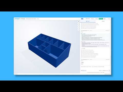
Describe a part made of these primitives and the CAD Agent writes the OpenSCAD for you, with adjustable sliders. The button only fills in the prompt.
Design a round cable grommet for a 60 mm desk hole: a 70 mm diameter flange 2 mm thick on top, a sleeve with a 58 mm outside diameter and 2 mm walls that goes 15 mm into the hole, and a 20 mm wide cable slot cut through the flange and sleeve. Make the hole size and slot width adjustable.
Frequently asked questions
How do I make a hollow cylinder (tube) in OpenSCAD?
Subtract a thinner cylinder from a thicker one: difference() { cylinder(h = 30, d = 24); translate([0, 0, -1]) cylinder(h = 32, d = 20); } gives a 2 mm wall. Make the inner cylinder 2 mm taller and start it 1 mm lower so it cuts cleanly through both ends.
How do I make a cone in OpenSCAD?
Give cylinder() two radii: cylinder(h = 30, r1 = 10, r2 = 0) is a pointed cone and cylinder(h = 20, r1 = 10, r2 = 5) is a truncated one. Use d1 and d2 for diameters. Always name them, because cylinder(20, 5) is read as h = 20, r1 = 5 and the default r2 = 1.
How do I make a hexagon in OpenSCAD?
Use cylinder(h = 5, d = 10, $fn = 6). The d value is the size across corners, and the size across flats is d × cos(30°), about 0.866 × d. For a nut that is 5.5 mm across flats, use d = 5.5 / cos(30), which is about 6.35 mm.
Why is my OpenSCAD sphere not the right size?
A sphere is built from rings of polygons with no vertex at the poles, so it comes out slightly short. sphere(10) with default settings is 19.89 mm tall instead of 20, and sphere(d = 20, $fn = 6) is only 17.32 mm. Raise $fn, or set $fa = 1 and $fs = 0.4, when the height matters.
Can OpenSCAD import STL files?
Yes. import("part.stl") loads STL, OFF, AMF and 3MF meshes (AMF and 3MF since 2019.05), and development snapshots add OBJ. The mesh should be closed and manifold if you want to cut or combine it. PrintPal's browser editor can't read files from your computer, so use desktop OpenSCAD for imports.
Related articles
Further reading
Tools for thisAll tools
Watch it doneVideo library
Thanks! We read every note and use them to decide what to update next.