OpenSCAD tutorial for beginners: build your first parametric part
OpenSCAD is free CAD software where you type a short script instead of drawing.
You place shapes like cube() and cylinder(), combine them with
union(), difference() and intersection(), and turn every
dimension into a variable. This tutorial teaches that whole core by building a
printable M3 L-bracket, and every example runs in your browser.
- Shapes:
cube,sphere,cylinderandpolyhedronmake solids. Sizes are in millimetres by convention. - Transforms:
translate,rotate,scaleandmirrorwrap the shape after them, with no semicolon in between. - Booleans:
difference()keeps the first child and cuts away the rest. That's how you make holes. - Parameters: put named variables at the top of the file and wrap repeated geometry in a
module. - Export: render, then save an STL or 3MF for your slicer.
What is OpenSCAD and why use it for 3D printing?
OpenSCAD is a script-based CAD program. There's no feature tree and no sketch tool like in Fusion or Onshape. You write code that describes solids, and OpenSCAD compiles it into a mesh you can slice. It's free and open source (GPL v2 or later) and runs on Windows, macOS and Linux.
- Everything is parametric. Dimensions are variables, so changing one number regenerates the whole part.
- Everything is text. Models diff cleanly in git, fit in a forum post, and are easy for an AI to write and edit.
- The trade-off: no clicking on faces, no constraint solver, and organic shapes are hard. It shines for brackets, boxes, mounts, spacers and anything with numbers in its spec.
The latest stable release is 2021.01 (February 2021). Nightly development snapshots are far newer and include the Manifold geometry engine, which renders many models dramatically faster. Release-candidate test builds numbered 2026.10 are on the official downloads page. Everything in this tutorial works in 2021.01. PrintPal's browser editor runs a 2025 development snapshot with Manifold switched on.
Set up: OpenSCAD in your browser or on your desktop
Pick one. The code is identical either way.
In the browser (no install)
- Click "Open in editor" on any code block below. It opens PrintPal's editor in Advanced mode with the code loaded.
- Edit and watch it re-render. Top-of-file variables also appear as sliders in the Params tab.
- Or start blank: open the CAD Agent, flip the Advanced toggle in the top bar and switch to Code mode.
On the desktop
- Download OpenSCAD from openscad.org/downloads (stable 2021.01, or a nightly snapshot).
- Create a new file and paste code into the editor pane.
- Press F5 to preview and F6 to do a full render before exporting.
Your first OpenSCAD model: hello, cube
The smallest useful OpenSCAD program is one shape and a semicolon:
cube([30, 20, 10]);
That's a box 30 mm along X, 20 mm along Y and 10 mm tall, with one corner on the origin.
cube(10) makes a 10 mm cube. Add center = true to centre it on
the origin instead:
cube([30, 20, 10], center = true);The core 3D shapes: cube, sphere and cylinder
Nearly every part starts from these. Full details are in the 3D primitives reference.
| Shape | Makes | Where it sits by default |
|---|---|---|
cube(size, center) | Box. size is a number or [x, y, z]. | Corner on the origin |
sphere(r) or sphere(d = …) | Ball | Centred on the origin |
cylinder(h, r | d, center) | Post, or a cone with r1/r2 or d1/d2 | Base on z = 0 |
polyhedron(points, faces) | Any closed solid from raw vertices | Wherever the points are |
cube([20, 20, 10]);                                        // box
translate([35, 10, 10]) sphere(d = 20);                    // ball resting on the bed
translate([60, 10, 0]) cylinder(h = 20, d = 16);           // round post
translate([85, 10, 0]) cylinder(h = 20, d1 = 16, d2 = 0); // conecylinder(20, 5) is not a 20 mm post with a 5 mm radius. The positional order is
h, r1, r2, and r2 defaults to 1, so you get a cone that narrows from
r = 5 to r = 1. Write cylinder(h = 20, r = 5).
Curves are really polygons. With the default settings ($fa = 12, $fs = 2)
a 3 mm hole has only 5 sides and a 20 mm disc has 30. Two lines at the top of a file fix that for every curve:
$fa = 1;      // min degrees per segment
$fs = 0.4;    // min segment length in mm

cylinder(h = 10, d = 3);                          // now 24 sides instead of 5
translate([10, 0, 0]) cylinder(h = 10, d = 3, $fn = 6); // $fn forces an exact count: a hexagon$fa/$fs over a global $fn.
They give small holes enough sides and big curves more, while a global $fn = 100
makes every tiny fillet slow to render. The OpenSCAD manual advises against $fn values above 128.
Move and rotate shapes with translate() and rotate()
A transform applies to the single shape (or { } block) that follows it. There's no semicolon
between the transform and its shape. More examples: transformations reference.
| Transform | What it does |
|---|---|
translate([x, y, z]) | Moves by that many millimetres |
rotate([x, y, z]) | Rotates in degrees around the origin: X first, then Y, then Z |
scale([x, y, z]) | Multiplies sizes (0.5 halves, 2 doubles) |
resize([x, y, z]) | Stretches to an exact size in mm |
mirror([1, 0, 0]) | Mirrors across the plane whose normal is that vector (here, flips X) |
color("orange") | Tints the preview only. Colour isn't saved in STL. |
translate([20, 0, 0]) cube(5);                     // moved 20 mm along +X
rotate([0, 0, 45]) cube(5);                         // spun 45° around Z
mirror([1, 0, 0]) translate([10, 0, 0]) cube(5);    // lands on the -X side
Transform order matters
Read a chain from the shape outward. Swapping two transforms usually moves the part somewhere else entirely:
// A: rotate the rod first, then move it. It lies along X from x = 20 to 30, resting on the bed.
translate([20, 0, 2]) rotate([0, 90, 0]) cylinder(h = 10, d = 4);

// B: same two steps, swapped. The move gets rotated too, so the rod ends up 20 mm below the bed.
rotate([0, 90, 0]) translate([20, 0, 2]) cylinder(h = 10, d = 4);
To transform several shapes at once, wrap them in braces:
translate([0, 0, 5]) {
  cube(10);
  translate([5, 5, 10]) sphere(3);
}
Combine shapes with union, difference and intersection
Booleans do most of the modelling work in OpenSCAD. There are three (full boolean guide):
union()merges its children into one solid. Shapes listed side by side at the top level are unioned for you.difference()keeps the first child and subtracts every child after it.intersection()keeps only the volume that all children share.
Drill a hole through a plate:
difference() {
  cube([40, 40, 4]);                                // the plate
  translate([20, 20, -1]) cylinder(h = 6, d = 6);   // the cutter, 1 mm past each face
}
And a dice blank, the overlap of a cube and a sphere:
intersection() {
  cube(20, center = true);
  sphere(d = 27, $fn = 96);
}If a cutter ends exactly on a face, the preview flickers and the result can keep a paper-thin skin
over the hole. Start it at z = -1 and make it 2 mm taller than the wall, as above.
What does difference() { A(); B(); C(); } produce?
The first child is the base and every later child is subtracted from it. Swap the order and you get a very different part.
Make it parametric with variables and modules
Name your dimensions once and reuse them everywhere:
plate_w = 40;
plate_t = 4;
hole_d  = 6;

difference() {
  cube([plate_w, plate_w, plate_t]);
  translate([plate_w / 2, plate_w / 2, -1])
    cylinder(h = plate_t + 2, d = hole_d);
}Each name holds one value per scope. Assign it twice and the last value wins everywhere in that scope, even on earlier lines, and OpenSCAD prints a warning. Use a new name for each new value.
A module is reusable geometry with its own parameters. A function returns a value:
module mounting_hole(d = 3.4, depth = 4) {
  translate([0, 0, -1]) cylinder(h = depth + 2, d = d, $fn = 32);
}

function inch(x) = x * 25.4;

difference() {
  cube([inch(2), inch(2), 4]);              // 50.8 × 50.8 × 4 mm plate
  for (x = [6, 44.8], y = [6, 44.8])
    translate([x, y, 0]) mounting_hole();   // four M3 clearance holes
}
Repeat with for loops and choose with if
A for loop places one copy of its body per value. Ranges are written [start : step : end], and the end is included:
for (x = [0 : 10 : 40])                 // 0, 10, 20, 30, 40
  translate([x, 0, 0]) cylinder(h = 5, d = 6, $fn = 32);

for (p = [[0, 20], [20, 20], [10, 35]])  // or loop over a list of points
  translate([p[0], p[1], 0]) cylinder(h = 5, d = 4, $fn = 32);
Use if to switch geometry on and off, and the ? : operator to pick a value:
rounded = true;
plate_h = rounded ? 4 : 3;     // ? : picks a value

if (rounded) {
  hull()
    for (x = [3, 27], y = [3, 17])
      translate([x, y, 0]) cylinder(h = plate_h, r = 3, $fn = 32);
} else {
  cube([30, 20, plate_h]);
}
That rounded plate uses hull(), which wraps the shapes in the tightest convex skin. Four cylinders in, one rounded rectangle out.
Build a parametric L-bracket in OpenSCAD, step by step
Time for a real part: an L-bracket for M3 screws with two holes in each leg. Tick the steps off as you go.
- Name the dimensions. Leg length, width, thickness and hole diameter go at the top, each with a comment so they show up as labelled sliders.
- Model one leg as a module.
plate()is a flatcubewith two holes cut out bydifference(). - Keep the holes clear of the corner. Holes at 45% and 80% of the leg leave room for a screw head next to the other leg.
- Reuse the module for the upright leg.
rotate([0, -90, 0])stands the plate up, andtranslate([thick, 0, 0])moves it onto the corner. - Union and render. Check that the holes go all the way through both legs.
- Export and print on its side. With the L flat on the bed, layer lines run around the corner, which is stronger than printing it standing up.
// L-bracket for M3 screws. All sizes in mm.

// Length of each leg
leg = 40;        // [20:80]
// Bracket width
width = 20;      // [10:40]
// Wall thickness
thick = 4;       // [2:8]
// Screw hole diameter (3.4 = M3 clearance)
hole_d = 3.4;
$fn = 48;

module plate() {
  difference() {
    cube([leg, width, thick]);
    // two holes, kept clear of the inside corner
    for (x = [leg * 0.45, leg * 0.8])
      translate([x, width / 2, -1])
        cylinder(h = thick + 2, d = hole_d);
  }
}

union() {
  plate();                                              // horizontal leg
  translate([thick, 0, 0]) rotate([0, -90, 0]) plate(); // vertical leg
}
Now change it. Every edit should take one number:
- Set
leg = 60and watch the holes move with it. - Set
thick = 6for a stiffer bracket. - Set
hole_d = 4.5to take M4 screws. - Challenge: add a triangular gusset at each edge. Hint:
hull()a flat thin cube and a standing thin cube.
In desktop OpenSCAD's Customizer (2019.05 and later, toggled from the Window menu), the comment line above a
variable becomes its label and a trailing // [20:80] sets the slider range. PrintPal's editor
reads the same top-of-file variables into its Params tab. Only plain values count, so leg = 40;
gets a slider but leg = 20 * 2; doesn't.
Why does each hole cylinder start at z = -1 with h = thick + 2?
A cutter that stops exactly at a face can leave a zero-thickness skin. Overshooting by 1 mm on each side guarantees a clean through-hole.
Export STL or 3MF from OpenSCAD for your slicer
- Desktop OpenSCAD: press F6 to render, then File → Export → Export as STL (F7). 3MF, OFF and AMF are in the same menu. A preview (F5) can't be exported.
- PrintPal editor: open the File menu and choose Export STL (binary) or Export 3MF (printable). Advanced mode adds Export STEP (faceted), Export OFF (text) and Export OpenSCAD source.
OpenSCAD works in meshes. PrintPal's STEP export is a faceted STEP, so every triangle becomes a flat face. Fusion, Onshape or FreeCAD will open it, but curves stay faceted and won't fillet like native CAD surfaces. Use STL or 3MF for printing. See 3D printing file formats for the differences.
Common OpenSCAD beginner mistakes and how to fix them
| Symptom | Cause | Fix |
|---|---|---|
| Parser error on the next line | Missing ; after a shape | End every shape statement with ; |
| Shape didn't move | translate([10, 0, 0]); cube(5); has a stray ; | No semicolon between a transform and its shape |
| Hole has a thin skin, or the preview flickers | Cutter ends exactly on a face | Overshoot by 1 mm on each side |
| Got a cone instead of a post | cylinder(20, 5) reads 5 as r1 | cylinder(h = 20, r = 5) |
| Screws won't fit | Default 5-sided small holes, and printed holes shrink | $fa = 1; $fs = 0.4; and clearance sizes such as 3.4 mm for M3 |
| Counter stays at 0 inside a loop | total = total + 1 makes a new local variable each pass | Compute the value with a list comprehension or a function |
| Part spins around the wrong point | rotate() always pivots on the origin | Rotate first, then translate |
| "Can't export STL" or a 2D-only error | Only 2D shapes at the top level | Wrap them in linear_extrude(height = …) |
Skip the typing: describe the bracket to the CAD Agent
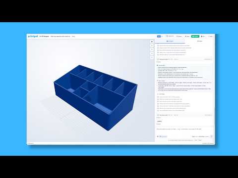
PrintPal's CAD Agent writes OpenSCAD from plain English, runs it in the same in-browser OpenSCAD (with BOSL2 and MCAD), and turns the parameters into sliders. Try the bracket you just built and compare its code with yours. The button only fills in the prompt. Nothing is sent until you press send.
Design an L-shaped wall bracket for M3 screws: two 40 mm legs at 90°, 20 mm wide and 4 mm thick, with two 3.4 mm through-holes in each leg placed so the screw heads clear the other leg. Make leg length, width, thickness and hole diameter adjustable parameters.
For prompts that produce clean, dimensioned parts, read the text-to-CAD prompting guide.
Frequently asked questions
Is OpenSCAD free?
Yes. OpenSCAD is free, open-source software (GPL v2 or later) for Windows, macOS and Linux. You can also use it in a browser: PrintPal's CAD Agent includes an OpenSCAD editor with the BOSL2 and MCAD libraries built in.
Is OpenSCAD hard to learn?
The core is small: four 3D shapes, a handful of transforms and three booleans. If you can write a spreadsheet formula, you can model a simple printable part in an afternoon. The real shift is thinking in solids you add and subtract instead of sketches you push and pull.
What units does OpenSCAD use?
OpenSCAD numbers have no units, but slicers read its STL and 3MF files as millimetres, so treat 1 unit as 1 mm. For an inch design, multiply by 25.4 or wrap the model in scale(25.4).
How do I export an STL from OpenSCAD?
In desktop OpenSCAD, press F6 to render, then choose File → Export → Export as STL (F7). A preview (F5) alone can't be exported. In PrintPal's browser editor, open the File menu and pick Export STL (binary) or Export 3MF (printable).
What is the latest version of OpenSCAD?
The latest stable release is OpenSCAD 2021.01. Nightly development snapshots add newer features and the much faster Manifold geometry engine, and release-candidate test builds numbered 2026.10 are on the official downloads page. Every example in this tutorial works in 2021.01 and later.
Related articles
Further reading
Tools for thisAll tools
Watch it doneVideo library
Thanks! We read every note and use them to decide what to update next.