By the PrintPal team
On this page
Key takeaways
- Start with a click-together build: an ESP32 board with a built-in screen, a printed case and firmware you flash from Chrome. No soldering, about 45 minutes, around $20.
- For your first wired project, an Arduino Uno R4 is the forgiving choice: 5 V logic matches most hobby sensors. Move to an ESP32 for Wi-Fi and an ESP32-S3 for native USB or a screen.
- ESP32 pins are 3.3 V. They tolerate 3.6 V at most, ADC2 pins stop working when Wi-Fi is on, and GPIO6 to 11 belong to the flash chip.
- Budget power first: 16 NeoPixels at full white draw 960 mA, almost twice what a USB 2.0 port supplies. Cap the current in code and add a capacitor.
- Match the filament to the place: PLA indoors, PETG near water, ASA in the sun. Measure every module with calipers before you design its case.
The short answer
The best first Arduino or ESP32 project with a 3D-printed case is one that needs no wiring: a board with a built-in screen dropped into a printed stand, flashed from the browser. Then build a weather station (two modules, four wires) and a NeoPixel lamp (your first power budget). Every project below has a parts list, wiring, code and print settings.
| Project | Board | Level | Soldering | Wi-Fi | Parts |
|---|---|---|---|---|---|
| 10 click-together builds | Waveshare ESP32-C6 or S3 screen boards | Beginner | No | Some | $18–32 |
| Weather station | ESP32 | Beginner | No | No | $20–35 |
| NeoPixel lamp | ESP32 | Beginner | Yes | No | $20–30 |
| Parking sensor | Arduino Uno R4 Minima | Beginner | No | No | $30–35 |
| Plant soil monitor | ESP32 | Intermediate | No | Yes | $20–25 |
| Useless box | ESP32 | Intermediate | Optional | No | $20–25 |
| USB macro pad | ESP32-S3 | Intermediate | Or hot-swap | No | $25–35 |
Parts costs are our estimates from board list prices plus typical module prices in November 2026. Build-guide costs are from each PrintPal guide.
Start here: ESP32 builds that click together
These PrintPal build guides use a single board with the screen already on it, so there is nothing to wire. Print the case, press the board in, and flash the program from Chrome or Edge.
Two boards cover all ten: the Waveshare ESP32-C6-LCD-1.47 (a 172 × 320 rectangular screen, Wi-Fi 6) and the Waveshare ESP32-S3-Touch-LCD-1.28 (a round 240 × 240 touch screen with a motion sensor). Each guide has the printable files, a parts list, step-by-step photos, the source code and a Flash to board button.
 No soldering
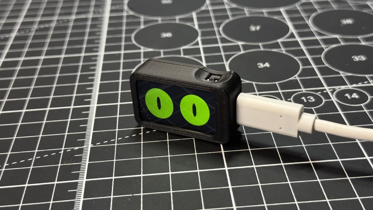
Slab eyes
Cartoon eyes in a tiny printed case that look around, blink, wink and doze off on their own.
Open the build guide
 No soldering
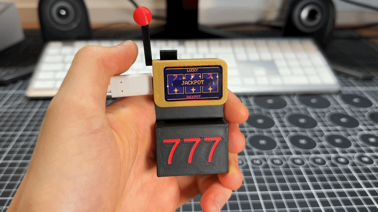
Lucky slab slot machine
A hand-sized slot machine with a real printed lever and three neon reels.
Open the build guide
 No soldering
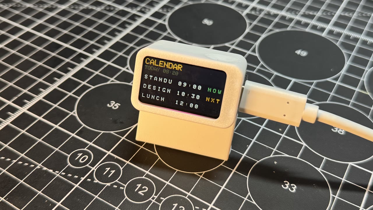
Split-flap departure slab
A desk-sized airport departures board where flights click in letter by letter.
Open the build guide
 No soldering
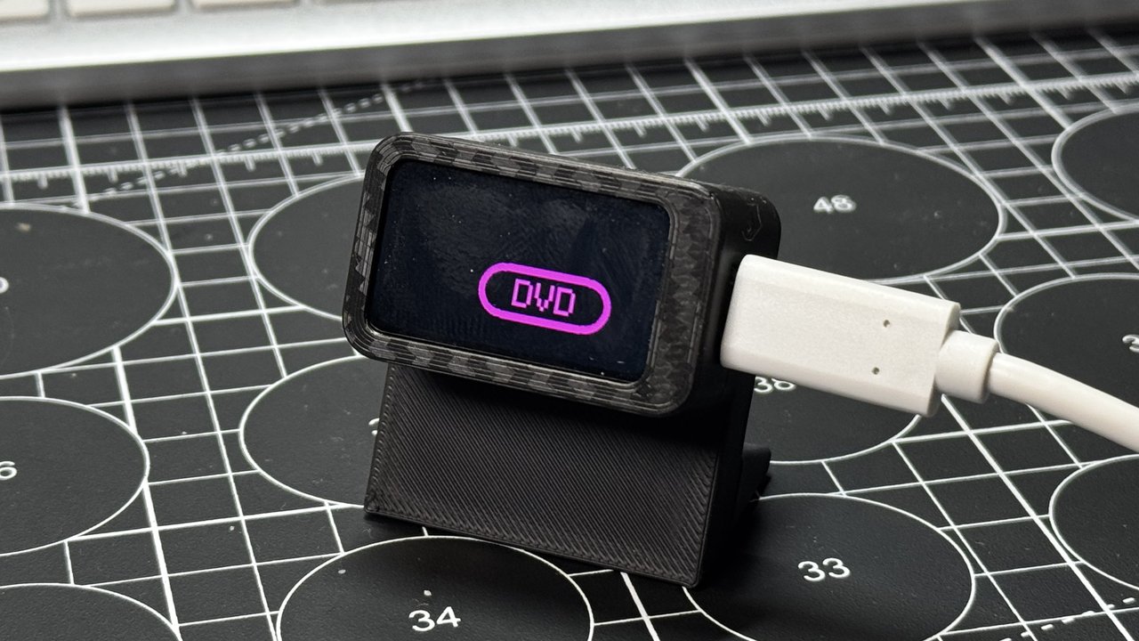
DVD screensaver slab
The bouncing DVD logo plus a running dino and a space invader, in a printed stand.
Open the build guide
 No soldering
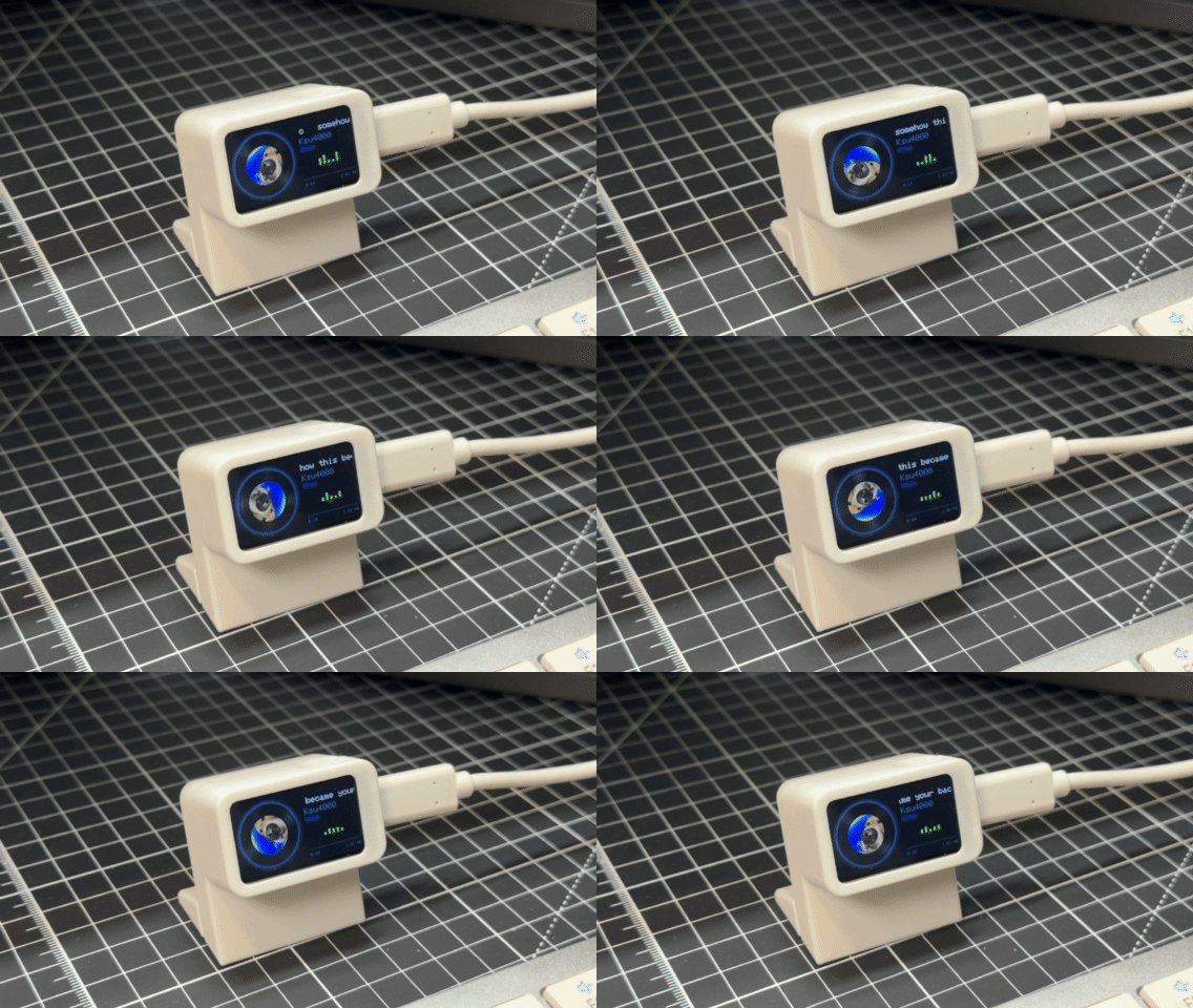
Music Play Pal
Shows the song playing on your PC with the album cover spinning like a record. One USB-C cable, no Wi-Fi.
Open the build guide
 No soldering
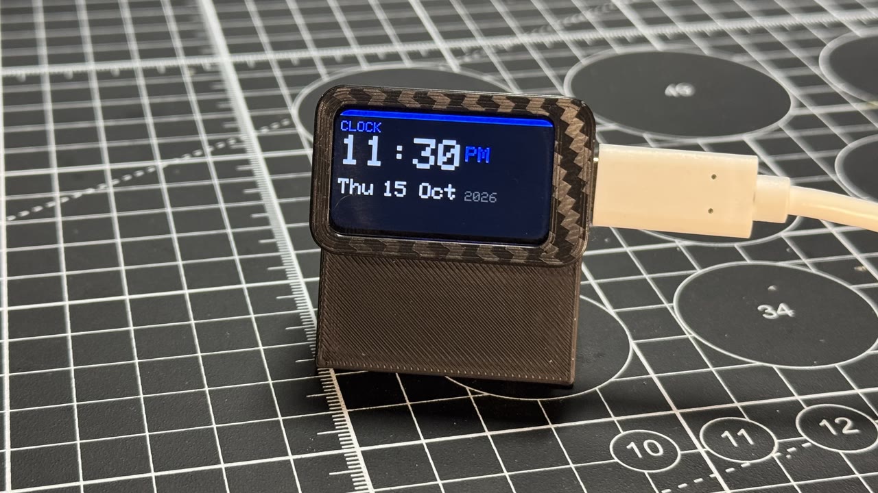
Desk command slab
Three pages on a tiny desk brick: a clock, today's weather, and a message you type on your phone.
Open the build guide
 No soldering
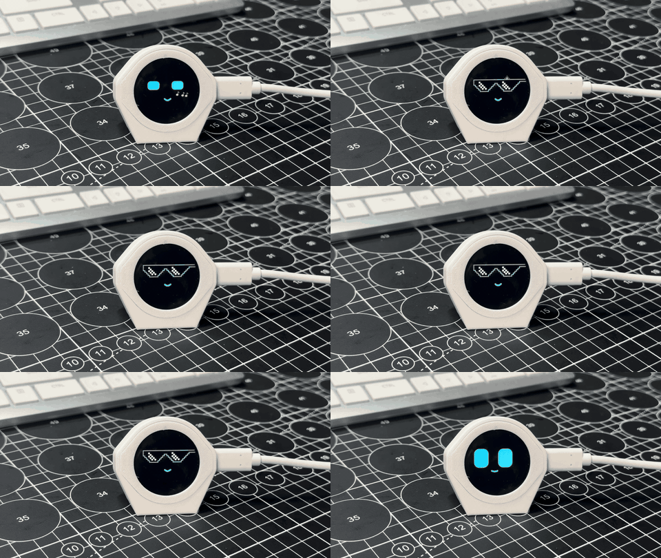
Desk Pal buddy
A desk pet with big eyes and real moods that reacts to taps, pets and shakes, and reminds you to drink water.
Open the build guide
 No soldering
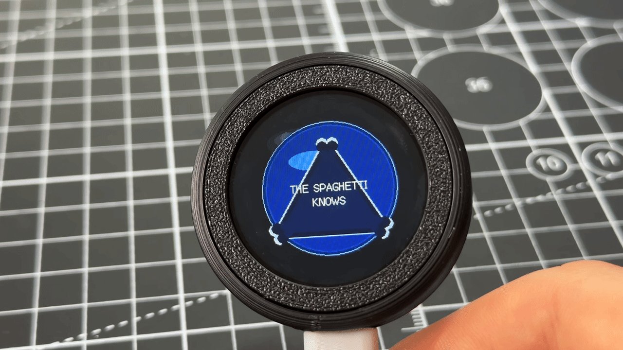
Desk Pal fortune 8-ball
A printed magic 8-ball: ask a question, shake or tap, and an answer swirls up.
Open the build guide
 No soldering
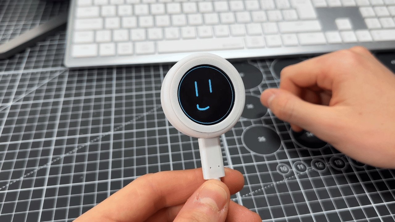
Desk Pal touch doodle
A round finger-painting pad: draw with a fingertip, hold still to change ink, shake to erase.
Open the build guide
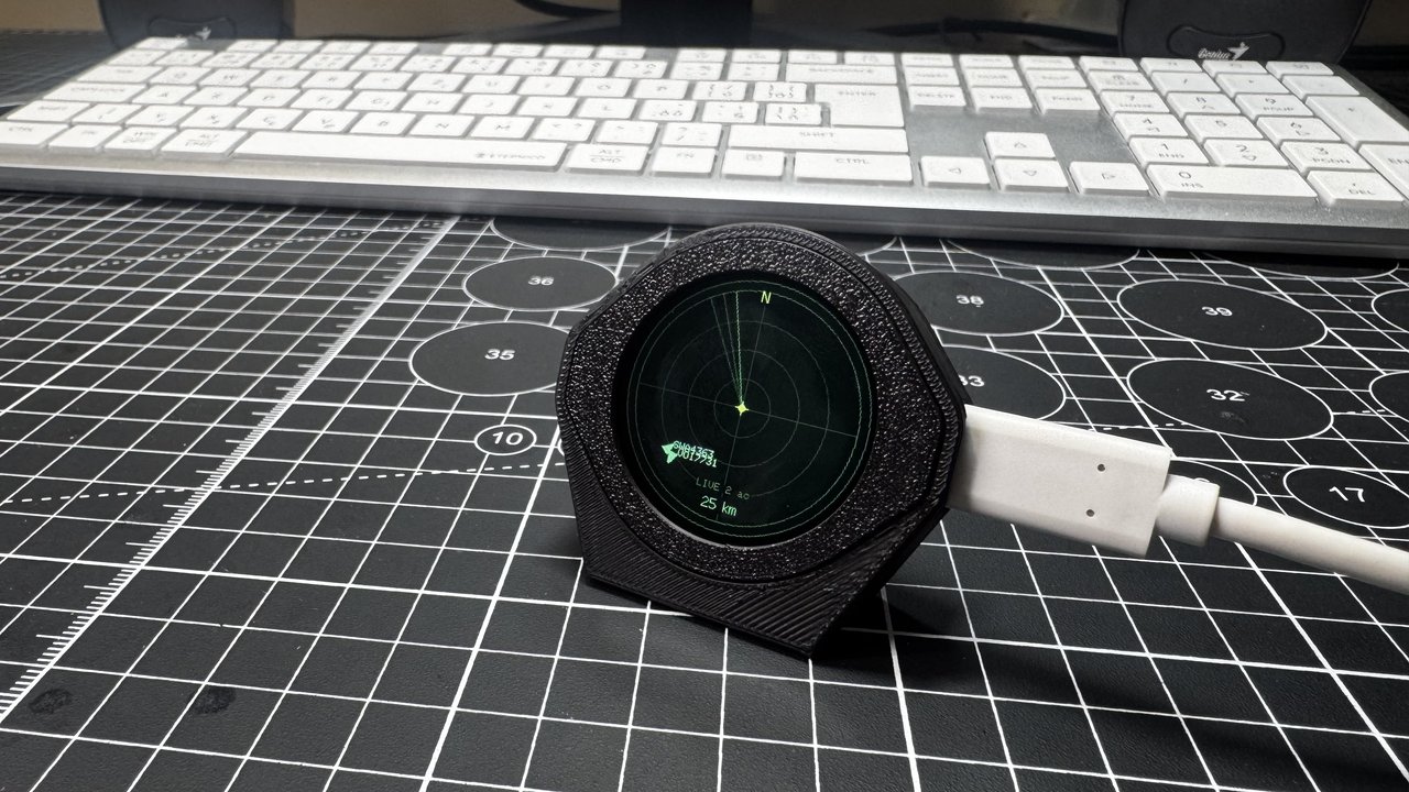 No soldering
Desk Pal plane radar
A radar scope that shows real planes flying near your home, with their callsigns.
Open the build guide
Choosing a board
Pick an Arduino Uno R4 for 5 V sensors and first projects, a classic ESP32 dev board when you need Wi-Fi on a budget, and an ESP32-S3 for native USB (keyboards, macro pads) or a screen. Every ESP32 runs its pins at 3.3 V.
| Board | Chip | Logic | Wireless | USB | Price |
|---|---|---|---|---|---|
| Arduino Uno R4 Minima | Renesas RA4M1, 48 MHz | 5 V | None | USB-C | $20 list |
| Arduino Uno R4 WiFi | RA4M1 plus ESP32-S3 | 5 V | Wi-Fi, Bluetooth | USB-C | $27.50 list |
| Arduino Nano ESP32 | ESP32-S3 (u-blox NORA-W106) | 3.3 V | Wi-Fi, Bluetooth | USB-C | $18.30 list |
| ESP32-DevKitC-32E | ESP32 | 3.3 V | Wi-Fi, Bluetooth 4.2 | Micro-USB | $15 (Adafruit) |
| ESP32-S3-DevKitC-1 | ESP32-S3 | 3.3 V | Wi-Fi, BLE | Native USB plus UART port | $19.95 (Adafruit, N8R8) |
| ESP32-C6-DevKitC-1 | ESP32-C6 | 3.3 V | Wi-Fi 6, BLE 5, Zigbee, Thread | Two USB-C | $9.95 (Adafruit) |
| Seeed XIAO ESP32-S3 | ESP32-S3, 8 MB PSRAM | 3.3 V | Wi-Fi, BLE 5 | USB-C | $7.49 |
| Seeed XIAO ESP32-C6 | ESP32-C6 | 3.3 V | Wi-Fi 6, Zigbee, Thread | USB-C | $5.20 |
| Raspberry Pi Pico 2 W | RP2350, 150 MHz | 3.3 V | Wi-Fi, Bluetooth 5.2 | Micro-USB | $7 at launch |
| Waveshare ESP32-S3-Touch-LCD-1.28 | ESP32-S3, round touch screen, IMU | 3.3 V | Wi-Fi, BLE 5 | USB-C | $29.99 (Amazon, sold by Waveshare) |
| Waveshare ESP32-C6-LCD-1.47 | ESP32-C6, 172 × 320 screen | 3.3 V | Wi-Fi 6, Bluetooth 5 | USB-C | $19.20 (Amazon, third-party listing) |
Arduino's US store showed sale prices on November 12, 2026; we list the regular prices. Espressif boards are often out of stock at Adafruit, and other distributors carry them.
Six wired projects, with code
Each project lists every part, shows the wiring as a diagram and a table, and gives a complete Arduino sketch with the libraries and board settings it needs. Use the chips to filter.
ESP32 weather station with a BME280 and an OLED
Temperature, humidity and air pressure on a 0.96-inch screen, updated every two seconds. Both modules share the same two I2C wires.
- Beginner
- 1 hour + printing
- $20–35 in parts
- How I2C lets two modules share two wires, each with its own address
- Reading a sensor library and printing formatted numbers
- Why a sensor sitting next to the ESP32 reads warm
Parts list
| Qty | Part | Why |
|---|---|---|
| 1 | ESP32 dev board | The brain; 3.3 V logic and Wi-Fi if you log data later |
| 1 | BME280 breakout, I2C | Temperature ±1 °C, humidity ±3%, pressure ±1 hPa. Not a BMP280, which has no humidity |
| 1 | SSD1306 OLED, 0.96", 128 × 64, I2C | About 20 mA; address 0x3C (or 0x3D by jumper) |
| 1 | Breadboard and 8 jumper wires | No soldering if the modules come with headers fitted |
| 1 | USB data cable | Power and upload |
| 30 g | PETG or ASA filament | For an outdoor case; PLA softens in the sun |
Wiring
| From | To | Wire | Note |
|---|---|---|---|
| ESP32 DevKitC 3V3 | BME280 VIN | Power | 3.3 V, not 5 V |
| ESP32 DevKitC GND | BME280 GND | Ground | |
| ESP32 DevKitC GPIO22 | BME280 SCL | Signal | I2C clock |
| ESP32 DevKitC GPIO21 | BME280 SDA | Signal | I2C data |
| ESP32 DevKitC 3V3 | OLED VCC | Power | |
| ESP32 DevKitC GND | OLED GND | Ground | |
| ESP32 DevKitC GPIO22 | OLED SCL | Signal | Same clock line |
| ESP32 DevKitC GPIO21 | OLED SDA | Signal | Same data line |
- Both modules hang off the same SDA and SCL lines; their addresses keep them apart.
- Breakout boards usually include the pull-up resistors I2C needs, so you add none.
Code
#include <Wire.h>
#include <Adafruit_GFX.h>
#include <Adafruit_SSD1306.h>
#include <Adafruit_BME280.h>

Adafruit_SSD1306 oled(128, 64, &Wire, -1);   // 128 x 64 pixels, no reset pin
Adafruit_BME280 bme;

void setup() {
  Serial.begin(115200);
  Wire.begin(21, 22);                          // SDA, SCL: the ESP32 defaults
  if (!oled.begin(SSD1306_SWITCHCAPVCC, 0x3C)) {
    Serial.println("OLED not found at 0x3C");
    while (true) delay(1000);
  }
  if (!bme.begin(0x76) && !bme.begin(0x77)) {  // breakouts use one or the other
    Serial.println("BME280 not found at 0x76 or 0x77");
    while (true) delay(1000);
  }
  oled.setTextColor(SSD1306_WHITE);
}

void loop() {
  float t = bme.readTemperature();             // degrees C
  float h = bme.readHumidity();                // % relative humidity
  float p = bme.readPressure() / 100.0F;       // Pa to hPa

  oled.clearDisplay();
  oled.setTextSize(2);
  oled.setCursor(0, 0);
  oled.printf("%.1f C\n", t);
  oled.setTextSize(1);
  oled.setCursor(0, 28);
  oled.printf("Humidity %.0f %%\n", h);
  oled.printf("Pressure %.0f hPa\n", p);
  oled.display();

  Serial.printf("%.2f C  %.1f %%  %.1f hPa\n", t, h, p);
  delay(2000);
}
Libraries: Adafruit BME280, Adafruit SSD1306 and Adafruit GFX from the Library Manager. Board: ESP32 Dev Module.
Build it
- Install the board package
In Arduino IDE, open Boards Manager, install esp32 by Espressif Systems and choose ESP32 Dev Module.
- Wire it on a breadboard
Follow the table. Both modules take power from 3V3.
- Upload and open the Serial Monitor
At 115200 baud. "Not found" usually means SDA and SCL are swapped.
- Check it reacts
Breathe on the sensor: humidity should jump within seconds.
- Move the sensor away from the board
Mount the BME280 at the end of a short cable or in its own vented chamber; the ESP32 warms the air around it by a few degrees.
Print settings: PETG or ASA, 0.2 mm layers, 3 walls, 20% infill. Print louvred rings flat, with no supports.
A Stevenson-screen style case: stacked louvred rings that let air through but keep sun and rain off the sensor, with the ESP32 and OLED in a separate box below. OLED module sizes vary between makers, so measure yours with calipers before designing the window. The CAD agent can draft both parts from a description with your measurements.
- If
bme.begin()fails at both addresses you may have a BMP280: it reports chip ID 0x58 where a BME280 reports 0x60.
NeoPixel desk lamp with a vase-mode shade
A ring of WS2812B LEDs under a printed shade, with warm white, rainbow and candle modes on one button. The code caps the current so a USB charger can run it safely.
- Beginner
- 1 hour + printing
- $20–30 in parts
- Why addressable LEDs need a power budget
- Protecting LEDs with a resistor and a capacitor
- Modes and a debounced button
Parts list
| Qty | Part | Why |
|---|---|---|
| 1 | ESP32 dev board | Drives the LEDs with FastLED; its BOOT button switches modes |
| 1 | WS2812B ring, 12 or 16 LEDs | Up to 60 mA per LED at full white: 960 mA for 16 |
| 1 | 330 Ω resistor | In the data line, close to the ring, to protect the first LED |
| 1 | 1000 µF capacitor, 6.3 V or higher | Across 5V and GND at the ring, to soak up the switch-on surge |
| 1 | 74AHCT125 level shifter (optional) | Lifts the 3.3 V data to 5 V if the first LED glitches |
| 1 | USB charger, 5 V | The code limits the LEDs to 450 mA |
| 40 g | White or natural PLA | For the shade; thin translucent walls diffuse best |
Wiring
| From | To | Wire | Note |
|---|---|---|---|
| ESP32 DevKitC GPIO16 | Resistor IN | Signal | Data from the ESP32 |
| Resistor OUT | LED ring DIN | Signal | Into the first LED |
| ESP32 DevKitC 5V | LED ring 5V | Power | From USB, through the board |
| ESP32 DevKitC GND | LED ring GND | Ground | A shared ground is required |
| Capacitor + | LED ring 5V | Power | Long leg to 5V |
| Capacitor - | LED ring GND | Ground | Striped side to GND |
- Power the ring from 5V, never from 3V3, and always join the grounds.
- The ESP32 sends 3.3 V data and WS2812B LEDs expect close to 5 V. It often works anyway, but Adafruit recommends a 74AHCT125 for reliable data.
Code
#include <FastLED.h>

#define DATA_PIN   16
#define NUM_LEDS   16
#define BUTTON_PIN 0        // the BOOT button on most ESP32 dev boards

CRGB leds[NUM_LEDS];
uint8_t mode = 0;           // 0 warm white, 1 rainbow, 2 candle
uint8_t hue = 0;

void setup() {
  pinMode(BUTTON_PIN, INPUT_PULLUP);
  FastLED.addLeds<WS2812B, DATA_PIN, GRB>(leds, NUM_LEDS);
  FastLED.setMaxPowerInVoltsAndMilliamps(5, 450);   // stay inside what USB can give
  FastLED.setBrightness(160);
}

void loop() {
  static bool wasDown = false;
  bool down = digitalRead(BUTTON_PIN) == LOW;
  if (down && !wasDown) {
    mode = (mode + 1) % 3;
    delay(30);                                      // crude debounce
  }
  wasDown = down;

  if (mode == 0) {
    fill_solid(leds, NUM_LEDS, CRGB(255, 147, 41)); // warm white, like a candle bulb
  } else if (mode == 1) {
    fill_rainbow(leds, NUM_LEDS, hue++, 255 / NUM_LEDS);
  } else {
    for (int i = 0; i < NUM_LEDS; i++) {
      leds[i] = CRGB(255, 120, 20);
      leds[i].nscale8(random8(120, 255));           // each LED flickers on its own
    }
  }
  FastLED.show();
  delay(mode == 2 ? 60 : 20);
}
Library: FastLED. setMaxPowerInVoltsAndMilliamps dims everything just enough to stay under 450 mA.
Build it
- Solder three wires to the ring
To 5V, GND and DIN. Put the resistor in the data wire, at the ring end.
- Add the capacitor
Across 5V and GND at the ring. The striped side is negative.
- Upload
Install FastLED, choose ESP32 Dev Module and upload. The ring glows warm white.
- Press BOOT to change mode
Warm white, rolling rainbow, candle flicker.
- Print the shade
Make one with the vase generator and print it in spiral vase mode.
Print settings: Shade: spiral vase mode with a 0.6 to 0.8 mm line width. Base: PLA, 0.2 mm, 3 walls, 15% infill.
Two parts: a round base that holds the ring face up with the board underneath, and a translucent shade printed in vase mode. Design the shade with the vase generator. Ring sizes differ between makers, so measure yours with calipers. Want no wiring at all? The LED lamp maker designs shades for Bambu Lab's LED Lamp Kit.
Adafruit gives up to 60 mA per LED at full-brightness white. FastLED scales brightness down to stay under the limit you set.
Garage parking sensor with an HC-SR04
An ultrasonic sensor on the garage wall beeps faster as the car gets closer, then holds a solid tone and a red light when it is time to stop.
- Beginner
- 1 hour + printing
- $30–35 in parts
- Timing an echo to measure distance
- Mapping one range of numbers onto another
- Why pin current limits matter
Parts list
| Qty | Part | Why |
|---|---|---|
| 1 | Arduino Uno R4 Minima | 5 V logic, so the HC-SR04 connects directly; $20 list |
| 1 | HC-SR04 ultrasonic sensor | 5 V, measures 2 cm to 4 m; most reliable from 10 to 250 cm |
| 1 | Passive piezo buzzer | tone() sets the pitch; an active buzzer beeps at one pitch only |
| 1 | Red LED | The stop light |
| 1 | 1 kΩ resistor | About 3 mA for the LED, well under the R4's 8 mA per pin |
| 1 | Breadboard and jumper wires | |
| 1 | USB-C cable and 5 V charger | Power in the garage |
Wiring
| From | To | Wire | Note |
|---|---|---|---|
| Uno R4 Minima 5V | HC-SR04 VCC | Power | |
| Uno R4 Minima GND | HC-SR04 GND | Ground | |
| Uno R4 Minima D9 | HC-SR04 TRIG | Signal | A 10 µs pulse starts a reading |
| Uno R4 Minima D10 | HC-SR04 ECHO | Signal | A 5 V pulse: fine on an Uno |
| Uno R4 Minima D6 | Resistor A | Signal | |
| Resistor B | LED + | Signal | Long leg |
| Uno R4 Minima GND | LED - | Ground | Short leg |
| Uno R4 Minima D5 | Buzzer + | PWM / signal | tone() output |
| Uno R4 Minima GND | Buzzer - | Ground |
- Using an ESP32 instead? Its pins take 3.6 V at most, so divide the ECHO signal: Adafruit uses two 10 kΩ resistors to bring 5 V down to 2.5 V.
- A magnetic buzzer can draw more than a pin should supply. Use a piezo, or drive it through a transistor.
Code
const int TRIG = 9;
const int ECHO = 10;
const int LED = 6;
const int BUZZER = 5;       // a passive piezo buzzer: tone() sets the pitch

void setup() {
  pinMode(TRIG, OUTPUT);
  pinMode(ECHO, INPUT);
  pinMode(LED, OUTPUT);
  Serial.begin(115200);
}

long readCm() {
  digitalWrite(TRIG, LOW);
  delayMicroseconds(2);
  digitalWrite(TRIG, HIGH);
  delayMicroseconds(10);                             // a 10 us pulse starts a reading
  digitalWrite(TRIG, LOW);
  unsigned long us = pulseIn(ECHO, HIGH, 30000UL);   // give up after 30 ms (about 5 m)
  if (us == 0) return -1;                            // nothing in range
  return us / 58;                                    // out and back: about 58 us per cm
}

void loop() {
  long cm = readCm();
  Serial.println(cm);

  if (cm < 0 || cm > 150) {                          // far away: stay quiet
    noTone(BUZZER);
    digitalWrite(LED, LOW);
    delay(100);
    return;
  }
  if (cm < 20) {                                     // stop here
    tone(BUZZER, 2000);
    digitalWrite(LED, HIGH);
    delay(100);
    return;
  }
  int gap = map(cm, 20, 150, 60, 600);               // closer means faster beeps
  tone(BUZZER, 2000, 50);
  digitalWrite(LED, HIGH);
  delay(50);
  digitalWrite(LED, LOW);
  delay(gap);
}
No libraries needed. Board: Arduino UNO R4 Minima (install Arduino UNO R4 Boards in Boards Manager).
Build it
- Wire it on a breadboard
Follow the table. Mind the LED's long leg (+).
- Upload and test on the bench
Move your hand toward the sensor: beeps speed up below 150 cm and turn solid under 20 cm.
- Set your stop distance
Park where you want to stop, read the distance in the Serial Monitor, and replace both 20s in the code with it.
- Mount it
At bumper height on the wall, pointing straight at the car.
Print settings: PLA or PETG, 0.2 mm, 3 walls, 15% infill. Print the front plate face down.
A front plate with two round holes for the transducers and a box behind it for the Uno. Measure the transducer diameter and spacing of your module with calipers before you design; clones vary. Keep the transducers flush with the front so the edges of the holes do not reflect the pulse.
Plant soil monitor with its own web page
A capacitive sensor in the pot and an ESP32 that serves a page to any phone on your Wi-Fi: moisture as a percentage, and a "water me" warning.
- Intermediate
- 1 hour + printing
- $20–25 in parts
- Analog readings and calibration
- Why ADC2 and Wi-Fi do not mix
- A tiny web server on a microcontroller
Parts list
| Qty | Part | Why |
|---|---|---|
| 1 | ESP32 dev board | Wi-Fi, plus ADC1 pins that keep working while Wi-Fi is on |
| 1 | Capacitive soil moisture sensor (SEN0193 design) | 3.3 to 5.5 V in, 0 to 3.0 V out, no exposed metal to corrode |
| 3 | Female-to-female jumper wires | |
| 1 | USB charger and cable | |
| 25 g | PETG filament | Copes with damp better than PLA |
Wiring
| From | To | Wire | Note |
|---|---|---|---|
| ESP32 DevKitC 3V3 | Soil sensor VCC | Power | |
| ESP32 DevKitC GND | Soil sensor GND | Ground | |
| ESP32 DevKitC GPIO34 | Soil sensor AOUT | Analog | Input-only pin on ADC1 |
- Use an ADC1 pin (GPIO32 to 39). ADC2 pins cannot be read while Wi-Fi is on.
- The reading goes down as the soil gets wetter.
Code
#include <WiFi.h>
#include <WebServer.h>

const char* WIFI_NAME = "your-network";       // 2.4 GHz only
const char* WIFI_PASS = "your-password";

const int SENSOR = 34;      // ADC1, so it keeps working while Wi-Fi is on
const int DRY = 3000;       // your reading in dry air
const int WET = 1300;       // your reading in a glass of water

WebServer server(80);

int moisture() {
  long sum = 0;
  for (int i = 0; i < 16; i++) { sum += analogRead(SENSOR); delay(5); }
  int raw = sum / 16;                                 // average out the noise
  return constrain(map(raw, DRY, WET, 0, 100), 0, 100);
}

void handleRoot() {
  int m = moisture();
  String html = "<!doctype html><meta name=viewport content='width=device-width'>"
                "<meta http-equiv=refresh content=10><title>Plant</title>"
                "<body style='font:24px system-ui;text-align:center;padding:40px'>"
                "<h1>" + String(m) + "%</h1><p>" +
                (m < 30 ? "Water me!" : "I'm fine, thanks.") + "</p>";
  server.send(200, "text/html", html);
}

void setup() {
  Serial.begin(115200);
  analogSetAttenuation(ADC_11db);                    // read the full 0 to ~3.1 V range
  WiFi.begin(WIFI_NAME, WIFI_PASS);
  while (WiFi.status() != WL_CONNECTED) { delay(500); Serial.print('.'); }
  Serial.printf("\nOpen http://%s\n", WiFi.localIP().toString().c_str());
  server.on("/", handleRoot);
  server.begin();
}

void loop() {
  server.handleClient();
  static unsigned long last = 0;
  if (millis() - last > 2000) {                      // raw readings, for calibrating
    last = millis();
    Serial.println(analogRead(SENSOR));
  }
}
Built-in libraries only. Replace DRY and WET with the readings the Serial Monitor shows for your sensor.
Build it
- Calibrate dry and wet
Upload, open the Serial Monitor and note the reading with the sensor in air (DRY) and in a glass of water up to its line (WET). Put both in the code.
- Add your Wi-Fi
Fill in WIFI_NAME and WIFI_PASS. The ESP32 joins 2.4 GHz networks only.
- Open the page
The Serial Monitor prints an address such as http://192.168.1.42. Open it on a phone on the same network.
- Seal the top edge
The electronics at the top of the sensor are not waterproof. Coat them with nail varnish or heat-shrink, and push the sensor in only up to its line.
- Fit the printed cap
It covers the electronics and the cable so watering cannot reach them.
Print settings: PETG, 0.2 mm, 3 walls, 20% infill.
A stake-shaped cap that slides over the top of the sensor and covers the electronics, with the cable leaving downward so water runs off. Keep the ESP32 in a small box out of the pot.
Useless box: flip the switch, a finger flips it back
The classic desk toy. Flip the toggle and a servo arm pops out of the lid to switch itself off, in one of three moods so it never gets old.
- Intermediate
- 2 hours + printing
- $20–25 in parts
- Driving a servo with PWM
- Reading a switch with a pull-up resistor
- Random behavior that feels alive
Parts list
| Qty | Part | Why |
|---|---|---|
| 1 | ESP32 dev board | Any ESP32 with a 5V pin |
| 1 | SG90 micro servo | 4.8 V, 1.8 kg·cm stall torque: plenty to flip a toggle |
| 1 | SPST toggle switch | Wired between GPIO14 and GND |
| 1 | 470 µF capacitor (optional) | Across the servo supply if the board resets when the servo moves |
| 1 | USB charger, 1 A or more | Laptop ports can sag when the servo starts |
| 80 g | PLA filament | Box, lid, flap and arm |
Wiring
| From | To | Wire | Note |
|---|---|---|---|
| ESP32 DevKitC 5V | SG90 VCC | Power | Red wire |
| ESP32 DevKitC GND | SG90 GND | Ground | Brown wire |
| ESP32 DevKitC GPIO13 | SG90 SIG | PWM / signal | Orange wire, PWM |
| ESP32 DevKitC GPIO14 | Switch A | Signal | INPUT_PULLUP |
| ESP32 DevKitC GND | Switch B | Ground |
- Power the servo from 5V, not 3V3. The 3.3 V signal from the ESP32 drives an SG90 fine.
- TowerPro rates the SG90 at 4.8 V and says 4.8 to 6 V is fine.
Code
#include <ESP32Servo.h>
#include <esp_random.h>

const int SERVO_PIN = 13;
const int SWITCH_PIN = 14;  // switch to GND: LOW means "on"
const int REST = 10;        // arm tucked inside the box, in degrees
const int PUSH = 150;       // arm far enough to flip the switch: tune this

Servo arm;

void setup() {
  pinMode(SWITCH_PIN, INPUT_PULLUP);
  randomSeed(esp_random());                     // a different mood order every power-up
  arm.setPeriodHertz(50);
  arm.attach(SERVO_PIN, 500, 2400);             // SG90 pulse range in microseconds
  arm.write(REST);
}

void sweep(int from, int to, int stepDelay) {
  int dir = from < to ? 1 : -1;
  for (int a = from; a != to; a += dir) { arm.write(a); delay(stepDelay); }
  arm.write(to);
}

void loop() {
  if (digitalRead(SWITCH_PIN) == HIGH) return;  // switch is off: nothing to do

  switch (random(3)) {
    case 0:                                     // polite
      sweep(REST, PUSH, 4);
      break;
    case 1:                                     // sneaky: peek, wait, strike
      sweep(REST, 90, 12);
      delay(random(600, 1800));
      sweep(90, PUSH, 2);
      break;
    default:                                    // annoyed: twice, fast
      arm.write(PUSH); delay(250);
      arm.write(110);  delay(150);
      arm.write(PUSH); delay(250);
  }
  delay(200);
  sweep(PUSH, REST, 3);
}
Library: ESP32Servo from the Library Manager. Raise PUSH until the arm just flips the switch without straining.
Build it
- Print the box first
You need it to find the servo angles.
- Mount the servo and switch
Servo under the flap, horn pointing at the switch; switch through the lid.
- Find REST and PUSH
Start with PUSH at 120 and raise it until the arm flips the switch cleanly.
- Upload and flip
Each flip picks one of three moods at random.
- Close it up
The arm lifts the hinged flap on its way out.
Print settings: PLA, 0.2 mm, 3 walls, 15% infill. Print the arm flat so the layers run along it.
A box with a hinged flap in the lid, a servo mount under the flap and a hole for the toggle. A print-in-place hinge saves hardware. SG90 clones vary slightly, so measure yours before designing the mount.
Three-key USB macro pad with an ESP32-S3
Three mechanical keys that type shortcuts on any computer with no driver: the ESP32-S3 shows up as a USB keyboard.
- Intermediate
- 1.5 hours + printing
- $25–35 in parts
- USB HID: how a board pretends to be a keyboard
- Edge detection for buttons
- Standard keyboard dimensions for printed plates
Parts list
| Qty | Part | Why |
|---|---|---|
| 1 | ESP32-S3 dev board with native USB | The S3 can act as a USB keyboard; the classic ESP32 cannot |
| 3 | MX-compatible mechanical switches | They clip into a 14 mm square plate cutout |
| 3 | MX-stem keycaps | |
| 1 | Hookup wire, or hot-swap sockets | One wire per key plus a shared ground |
| 40 g | PLA or PETG | Plate and case |
Wiring
| From | To | Wire | Note |
|---|---|---|---|
| ESP32-S3 DevKitC-1 GPIO4 | Key 1 A | Signal | |
| ESP32-S3 DevKitC-1 GND | Key 1 B | Ground | |
| ESP32-S3 DevKitC-1 GPIO5 | Key 2 A | Signal | |
| ESP32-S3 DevKitC-1 GND | Key 2 B | Ground | |
| ESP32-S3 DevKitC-1 GPIO6 | Key 3 A | Signal | |
| ESP32-S3 DevKitC-1 GND | Key 3 B | Ground |
- Each switch connects its pin to ground; INPUT_PULLUP holds the pin HIGH until you press.
- GPIO4, 5 and 6 are not strapping pins on the S3, so they are safe for keys.
Code
#include "USB.h"
#include "USBHIDKeyboard.h"

USBHIDKeyboard Keyboard;

const int KEYS[3] = {4, 5, 6};     // each switch connects its pin to GND
bool wasDown[3] = {false, false, false};

void setup() {
  for (int i = 0; i < 3; i++) pinMode(KEYS[i], INPUT_PULLUP);
  Keyboard.begin();
  USB.begin();
}

void press(int i) {
  switch (i) {
    case 0:                                       // copy
      Keyboard.press(KEY_LEFT_CTRL); Keyboard.press('c');
      break;
    case 1:                                       // paste
      Keyboard.press(KEY_LEFT_CTRL); Keyboard.press('v');
      break;
    case 2:                                       // type a snippet
      Keyboard.print("Printed on my own macro pad!");
      return;
  }
  delay(20);
  Keyboard.releaseAll();
}

void loop() {
  for (int i = 0; i < 3; i++) {
    bool down = digitalRead(KEYS[i]) == LOW;
    if (down && !wasDown[i]) press(i);
    wasDown[i] = down;
  }
  delay(5);                                       // simple debounce
}
Board: ESP32S3 Dev Module, USB Mode: USB-OTG (TinyUSB). On a Mac use KEY_LEFT_GUI (Command) instead of KEY_LEFT_CTRL.
Build it
- Print the plate and case
The 1.5 mm plate is what the switch clips grip.
- Snap in the switches
Push from the top until they click.
- Wire the keys
One leg of each switch to its GPIO, the other legs together to GND.
- Set USB mode and upload
USB Mode: USB-OTG (TinyUSB). Upload through the UART port, then plug the port labelled USB into the computer.
- Try it
Open a text editor and press key 3.
Print settings: PLA or PETG, 0.2 mm, 4 walls; print the plate flat so the cutouts stay square.
A 1.5 mm plate with three 14 × 14 mm square cutouts spaced 19.05 mm apart, the standard key pitch, on a case deep enough for the board and wires. Leave an opening for the USB port and the BOOT button.
ESP32 rules that save hours of debugging
| Rule | Why | Do this |
|---|---|---|
| Pins are 3.3 V, not 5 V tolerant | Espressif rates GPIO at 3.6 V maximum | Divide or level-shift 5 V signals, such as an HC-SR04 echo |
| ADC2 stops when Wi-Fi is on | Wi-Fi uses the ADC2 hardware | Read analog sensors on ADC1: GPIO32 to 39 |
| GPIO34 to 39 are input only | No output driver, no internal pull-ups | Use them for sensors; add external pull-ups |
| Strapping pins: GPIO0, 2, 5, 12, 15 | Their level at power-up sets the boot mode | Avoid parts that pull them high or low at boot |
| GPIO6 to 11 belong to the flash | They connect to the SPI flash chip on most modules | Never use them |
| Default I2C is SDA 21, SCL 22 | Set in the Arduino ESP32 core | Use them unless you need others |
| Uno R4 pins supply 8 mA | Arduino's specification for the R4 Minima | Use 1 kΩ for LEDs; a transistor for more |
Designing the printed enclosure
- Measure, do not trust drawings. Module sizes vary between makers. Measure every board with calipers, then add clearance: 0.2 to 0.4 mm per side is a good start on FDM printers.
- Make the USB opening generous. Plugs have overmoulds that are bigger than the port.
- Plan for heat. Give regulators and the ESP32 some air, and keep temperature sensors away from both.
- Print faces down. Front plates and windows come out cleanest printed face-first on the bed.
- Use inserts or bosses for screws. Heat-set inserts survive repeated opening; self-tapping screws into bare plastic wear out.
- Pick the material for the place. See the table below.
| Material | Use it for | Avoid |
|---|---|---|
| PLA | Indoor gadgets, desk toys, prototypes | Cars, windowsills, outdoors: it softens in heat |
| PETG | Damp places, planters, garages | Very fine detail (it strings more) |
| ASA | Outdoor cases in sunlight | Printing without an enclosure and ventilation |
| TPU | Feet, bumpers, gaskets, cable strain relief | Rigid parts |
Do not want to model it yourself? Describe the box with your measurements to the CAD agent, or start from a PrintPal maker for the round ESP32-S3 screen.
 AI
AI CAD agent
Describe a part with real dimensions and get parametric OpenSCAD you can edit, with a live preview and STL export.
 Desk Pal maker
Design a printed head for the round ESP32-S3 screen.
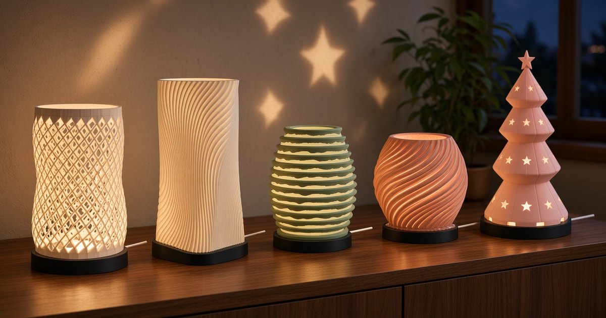 LED lamp maker
Design a shade for the Bambu Lab LED Lamp Kit 001.
 ESP32 web flasher
Flash firmware to an ESP32 from Chrome or Edge, nothing to install.
 Filament finder
Pick a material by strength, heat, flex and ease of printing.
 Bin generator
Storage bins and drawer organizers sized to the millimetre.
Getting code onto the board
- Install Arduino IDE
Version 2.3.11 is current (November 12, 2026). Arduino Cloud's free plan also has an online editor.
- Add the board package
esp32 by Espressif Systems for ESP32 boards, Arduino UNO R4 Boards for the Uno R4.
- Use a data cable
If no port appears, swap the cable before anything else.
- Enter download mode if needed
Hold BOOT, tap RESET, release BOOT, then upload again.
- Or skip the IDE
PrintPal build guides include precompiled firmware for the ESP32 web flasher: plug in, click, done.
- Simulate first
Wokwi simulates ESP32 and Arduino projects in the browser, free with unlimited public projects, so you can test code before the parts arrive.
Frequently asked questions
What is a good first ESP32 project?
One with no wiring: an ESP32 board with a built-in screen in a printed case, flashed from the browser, such as PrintPal's Slab eyes or Desk Pal buddy builds. After that, an ESP32 weather station with a BME280 and an OLED teaches I2C with just four wires.
Should I start with Arduino or ESP32?
Start with an Arduino Uno R4 if your sensors are 5 V parts, because its pins run at 5 V. Choose an ESP32 for Wi-Fi or Bluetooth, and an ESP32-S3 for native USB or a screen. Both use the Arduino IDE.
Can I connect a 5 V sensor to an ESP32?
Power it from 5 V if it needs that, but never feed a 5 V signal into an ESP32 pin: they are rated for 3.6 V at most. Use a voltage divider (Adafruit uses two 10 kΩ resistors on the HC-SR04 echo pin) or a level shifter.
Why does my ESP32 reset when the servo moves?
The servo pulls a burst of current that makes the supply voltage dip. Power the servo from 5V rather than 3V3, use a stronger USB charger, and add a large capacitor (around 470 µF) across the servo supply.
What filament is best for electronics enclosures?
PLA for indoor projects, PETG for damp places such as planters and garages, and ASA for outdoor cases in sunlight. PLA softens in heat, so keep it out of cars and windowsills.
Do I need to solder for these projects?
Not for the ten click-together builds, the weather station, the parking sensor or the soil monitor if your modules come with headers fitted. The NeoPixel lamp needs three wires soldered to the ring, and the macro pad needs soldering or hot-swap sockets.
How do I flash an ESP32 from the browser?
Open a web flasher in Chrome or Edge, connect the board with a USB data cable, pick its port and click Install. PrintPal's ESP32 web flasher and every PrintPal build guide work this way. If no port appears, hold BOOT, tap RESET and try again.
Sources and method
Board specifications and prices come from the makers' and distributors' own pages (Arduino, Espressif, Adafruit, Seeed, Raspberry Pi, Waveshare) on November 12, 2026. Electrical limits come from Espressif's documentation and the part makers' datasheets listed below. The code was written for this guide against the current Arduino cores and the libraries named in each project. Parts costs are estimates. The ten click-together builds are PrintPal's own build guides.
- Arduino Uno R4 Minima · 5 V logic, 8 mA per pin
- Arduino Uno R4 WiFi
- Arduino Nano ESP32
- ESP32-DevKitC user guide
- ESP32-S3-DevKitC-1 user guide
- ESP32-C6-DevKitC-1 user guide
- Adafruit ESP32-DevKitC-32E
- Seeed XIAO ESP32-S3
- Seeed XIAO ESP32-C6
- Raspberry Pi Pico 2 W launch
- Waveshare ESP32-S3-Touch-LCD-1.28 wiki
- Waveshare ESP32-C6-LCD-1.47 wiki
- ESP32-S3-Touch-LCD-1.28 on Amazon (B0CM68M8LR)
- Espressif ESP-FAQ: hardware design · 3.6 V GPIO limit
- ESP-IDF GPIO reference · ADC2, input-only and strapping pins
- Arduino ESP32 core pin map
- Adafruit: powering NeoPixels
- Adafruit: NeoPixel best practices
- SparkFun HC-SR04
- Adafruit HC-SR04 · echo divider
- TowerPro SG90
- Adafruit BME280
- Adafruit SSD1306 OLED
- DFRobot SEN0193 datasheet
- TP4056 datasheet
- Adafruit: Li-ion and LiPoly protection
- Arduino IDE releases
- Wokwi pricing
Spotted something out of date? Tell us and we will re-check it.